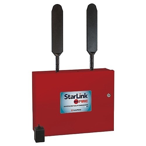
COMMERCIAL DUALPATH FIRE/BURG
Product Info
The StarLink MAX Series Sole/Dual-Path Commercial / Residential Fire alarm capture IP communicators are fully supervised, wireless digital two-way subscriber units. The SLE-MAXVI-CFB and SLE-MAXVI-CFBPS communicators operate on the Verizon network, the SLE-MAXAI-CFB and SLE-MAXAI-CFBPS on the AT&T network and all models utilize CAT-M1 technology. These devices support both Sole Path and Dual Path communication. Sole Path communication is cellular only and Dual Path communication is cellular and IP, which requires connection to the local network using the on-board Ethernet jack or via Wi-Fi using the optional UL 864 Certified SLE-WIFI-MODULE.
Features:
Power limited output to the StarLink communicator PC board 12V input terminals
Battery connection red and black flying leads
Monitored battery charging and Active battery test circuits
StarLink communicator trouble input (from StarLink PC-board PGM1 terminal to detect StarLink communicator trouble)
Requires a sealed lead acid min 4AH / max 7AH battery for minimum 24-hour standby time (max charge current 200mA)
Trouble relay output (C, N/O and N/C terminals) to wire to a panel zone dedicated to “Communicator Trouble” (dry contacts). Remove jumper “J2” isolate relay OUT1 common from ground
Green AC ON LED visible from the exterior housing
Yellow TROUBLE LED “D4” on PC board. Flashes signify:One flash: AC fail / brownout
Two flashes: Low battery
Three flashes: Charging circuit trouble
Four flashes: StarLink communicator trouble
Specifications:
Electrical Ratings for 120VAC, 60Hz For Models with Power Supply (SLE-MAXVI-CFBPS and SLE-MAXAI-CFBPS)
Input Voltage – 120VAC nominal
Input Current – 200mA maximum
Maximum Charging Current – 200mA
Electrical Ratings for +12V / 24V For Models without Power Supply (SLE-MAXVI-CFB and SLE-MAXAI-CFB)†
Input Voltage – 10-24VDC regulated (power-limited output from UL Certified control panel Aux/Remote Fire Power)
Input Current – 10VDC standby: 115mA, 12VDC standby: 101mA, 15VDC standby: 92mA, 24VDC standby: 85mA
Wi-Fi Module – (Optional) Add 45mA to the above, (With peak RF transmission current of 325mA)
Electrical Ratings for the IN 1 Fire Input
Input Voltage – 9-25VDC
Maximum Input Current – Up to 2mA from FACP NAC circuit
Electrical Ratings for IN 2, IN 3, IN 4, and IN 5: (Inputs IN 2, IN 3, IN 4, and IN 5 are Class B)
Maximum Loop Voltage – 25VDC
Maximum Loop Current – 1.2mA
End of Line Resistor (EOLR) Value – 10K (2 req’d)
Electrical Ratings for PGM3 Output
Open Collector Output – Maximum Voltage 3V when active; 25V maximum when not active
Maximum PGM Sink Current – 50mA (up to 15VDC), 25mA (15.1VDC – 25VDC)
Physical (W


